555 Timer Circuit Schematic : Repeating Timer Using Two 555 Timer Ic S / In this project, we will show how to build a simple led flasher circuit using a 555 timer chip.
555 Timer Circuit Schematic : Repeating Timer Using Two 555 Timer Ic S / In this project, we will show how to build a simple led flasher circuit using a 555 timer chip.. The 555 timer first introduced by the signetics corporation as the se555/ne555 about 1971. The 555 timer chip is a very versatile ic, because when connected correctly, it can it can create pulses of current at specific time intervals decided. In this circuit, we will connect the 555 timer to be in astable mode. In this project, we will show how to build a simple led flasher circuit using a 555 timer chip. Oct 26, 2020 · a blinking led circuit.
The 555 timer can be obtained very cheaply from pretty much any electronic retailer. In other words, 555 timer is a circuit which may be connected as a stable or monostable multivibrator. The 555 timer ic is an integrated circuit used in a variety of timer, pulse generation and oscillator applications. Then the bistable 555 timer is stable in both states, "high" and "low". This 555 timer circuit will remain in either state indefinitely and is therefore bistable.
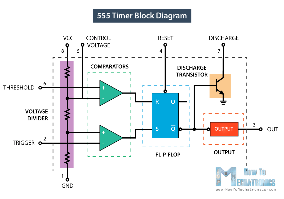
555 Timer Ic Working Principle Block Diagram Circuit Schematics from howtomechatronics.com The 555 timer ic is an integrated circuit used in a variety of timer, pulse generation and oscillator applications. In other words, 555 timer is a circuit which may be connected as a stable or monostable multivibrator. In this project, we will show how to build a simple led flasher circuit using a 555 timer chip. The 555 timer chip is a very versatile ic, because when connected correctly, it can it can create pulses of current at specific time intervals decided. Oct 26, 2020 · a blinking led circuit. This 555 timer circuit will remain in either state indefinitely and is therefore bistable. In this circuit, we will connect the 555 timer to be in astable mode. The 555 timer can be obtained very cheaply from pretty much any electronic retailer.
The threshold input (pin 6) is connected to ground to ensure that it cannot reset the bistable circuit as it would in a normal timing application.
Oct 26, 2020 · a blinking led circuit. This 555 timer circuit will remain in either state indefinitely and is therefore bistable. The 555 timer can be obtained very cheaply from pretty much any electronic retailer. Working and schematic diagram of clap swith circuit Jun 26, 2021 · hi, i'm trying to build a 555 timer circuit that has an output low time of 5 minutes and an output high time of 250 milliseconds. The values of r1, r2, and c1 affect the speed of the blinking. In this project, we will show how to build a simple led flasher circuit using a 555 timer chip. I cant seem to find a good example online. The following schematic shows two additions to the basic 555 timer circuit. To observe the 555 timer in astable mode, let's build a circuit that uses the 555 timer's oscillating output to make an led flash on and off: One reduces the trigger sensitivity and the other will double the output pulse duration without increasing the values of r1 and c1. In more simple words, 555 timer is a monolithic timing circuit, which can produce accurate timing pulses with 50% or 100% duty cycle. The threshold input (pin 6) is connected to ground to ensure that it cannot reset the bistable circuit as it would in a normal timing application.
One reduces the trigger sensitivity and the other will double the output pulse duration without increasing the values of r1 and c1. The 555 timer ic is an integrated circuit used in a variety of timer, pulse generation and oscillator applications. It was developed in the year 1970 by signetic corporation and designed by hans camenzind in 1971. The 555 timer can be obtained very cheaply from pretty much any electronic retailer. In more simple words, 555 timer is a monolithic timing circuit, which can produce accurate timing pulses with 50% or 100% duty cycle.
555 Timer from sound-au.com In more simple words, 555 timer is a monolithic timing circuit, which can produce accurate timing pulses with 50% or 100% duty cycle. Working and schematic diagram of clap swith circuit I have used two 555 timer ics in this project and both these 555 ics act as. The 555 timer chip is a very versatile ic, because when connected correctly, it can it can create pulses of current at specific time intervals decided. Jun 26, 2021 · hi, i'm trying to build a 555 timer circuit that has an output low time of 5 minutes and an output high time of 250 milliseconds. This 555 timer circuit will remain in either state indefinitely and is therefore bistable. It was developed in the year 1970 by signetic corporation and designed by hans camenzind in 1971. Oct 13, 2018 · this circuit produces a sound similar to the police siren.
The threshold input (pin 6) is connected to ground to ensure that it cannot reset the bistable circuit as it would in a normal timing application.
If you want to know all the pinout of the 555 timer, what each pin is and what each pin does, see 555 timer pinout. Working and schematic diagram of clap swith circuit The 555 timer first introduced by the signetics corporation as the se555/ne555 about 1971. The 555 timer ic is an integrated circuit used in a variety of timer, pulse generation and oscillator applications. One reduces the trigger sensitivity and the other will double the output pulse duration without increasing the values of r1 and c1. Then the bistable 555 timer is stable in both states, "high" and "low". Jun 26, 2021 · hi, i'm trying to build a 555 timer circuit that has an output low time of 5 minutes and an output high time of 250 milliseconds. I cant seem to find a good example online. In more simple words, 555 timer is a monolithic timing circuit, which can produce accurate timing pulses with 50% or 100% duty cycle. Oct 13, 2018 · this circuit produces a sound similar to the police siren. In other words, 555 timer is a circuit which may be connected as a stable or monostable multivibrator. Oct 26, 2020 · a blinking led circuit. To observe the 555 timer in astable mode, let's build a circuit that uses the 555 timer's oscillating output to make an led flash on and off:
In other words, 555 timer is a circuit which may be connected as a stable or monostable multivibrator. The following schematic shows two additions to the basic 555 timer circuit. One reduces the trigger sensitivity and the other will double the output pulse duration without increasing the values of r1 and c1. The threshold input (pin 6) is connected to ground to ensure that it cannot reset the bistable circuit as it would in a normal timing application. I cant seem to find a good example online.
Ic 555 Timer Working Pin Diagram Specifications Features from www.electronicsforu.com I have used two 555 timer ics in this project and both these 555 ics act as. I cant seem to find a good example online. Oct 26, 2020 · a blinking led circuit. One reduces the trigger sensitivity and the other will double the output pulse duration without increasing the values of r1 and c1. In this circuit, we will connect the 555 timer to be in astable mode. The values of r1, r2, and c1 affect the speed of the blinking. Oct 13, 2018 · this circuit produces a sound similar to the police siren. To observe the 555 timer in astable mode, let's build a circuit that uses the 555 timer's oscillating output to make an led flash on and off:
In more simple words, 555 timer is a monolithic timing circuit, which can produce accurate timing pulses with 50% or 100% duty cycle.
I have used two 555 timer ics in this project and both these 555 ics act as. To observe the 555 timer in astable mode, let's build a circuit that uses the 555 timer's oscillating output to make an led flash on and off: Oct 13, 2018 · this circuit produces a sound similar to the police siren. This 555 timer circuit will remain in either state indefinitely and is therefore bistable. The values of r1, r2, and c1 affect the speed of the blinking. One reduces the trigger sensitivity and the other will double the output pulse duration without increasing the values of r1 and c1. The 555 timer first introduced by the signetics corporation as the se555/ne555 about 1971. I cant seem to find a good example online. The 555 timer chip is a very versatile ic, because when connected correctly, it can it can create pulses of current at specific time intervals decided. The following schematic shows two additions to the basic 555 timer circuit. Then the bistable 555 timer is stable in both states, "high" and "low". Jun 26, 2021 · hi, i'm trying to build a 555 timer circuit that has an output low time of 5 minutes and an output high time of 250 milliseconds. In more simple words, 555 timer is a monolithic timing circuit, which can produce accurate timing pulses with 50% or 100% duty cycle.
The 555 timer ic is an integrated circuit used in a variety of timer, pulse generation and oscillator applications 555 timer schematic. In this circuit, we will connect the 555 timer to be in astable mode.


0 Komentar